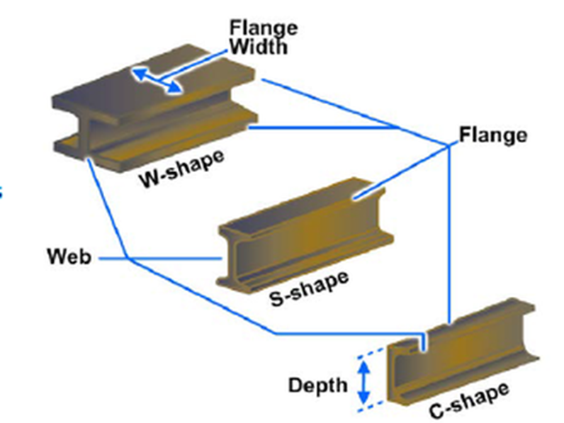
Steel beam is a structural element which can resist only the applied bending moments. Most common types of steel beam sections include W shape, S shape and C shapes.
In this article, we will see the steel beam design process as per the guidelines of ANSI/AISC 360-16 Specification for Structural Steel Buildings.
Before we dig in and understand the beam design in bending, it is first important to understand the cross section classification.
Steel beam cross section classification
A steel beam’s cross section under the action of flexure stresses due to bending can be either classified as:
- Compact
- Non-compact
- Slender
This classification is different than the case of columns, where elements of cross section under the action of uniform compressive stress are either classified as slender or non slender.
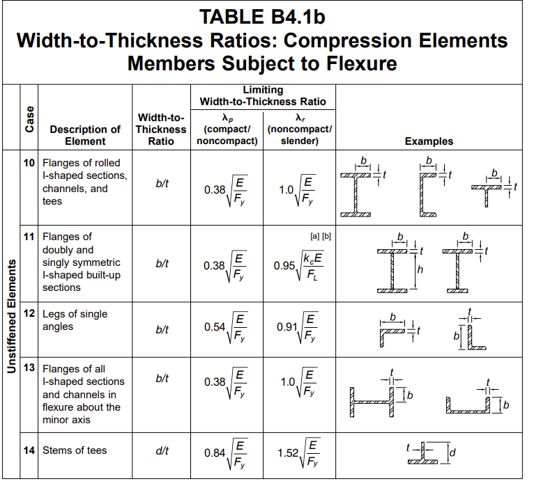
A steel cross section under the flexure stress means that some part of the cross section would be in tension and some would be in compression. You will only need to classify the elements (webs or flanges) of cross section in compression. Following flow chart can be used to classify compressed webs or flanges of beams in flexure. In particular, the slenderness ratio of each element is compared against the limiting value of slenderness ratio (λp). λp is given in Table B4.1b of ANSI/AISC 360-16 Specification for Structural Steel Buildings. (Note: Two set of tables are given for stiffened and unstiffened compression elements)

Most of the beam sections can be classified as fully compact, therefore we will be fist discussing the design of Doubly symmetric compact I-shaped members and channels bent about their major axis.
For other types of cross sections, you are referred to ANSI/AISC 360-16 Specification for Structural Steel Buildings.
Beam behaviour under bending
A beam can behave in three different manners which are identified as Zone 1, 2 and 3 bending cases as shown in following diagram. These three different behaviours are identified by comparing the unbraced length of compressed part of beam (Lb) with limits on length Lp and Lr.
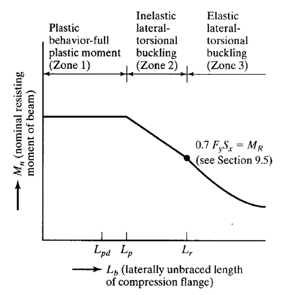
Zone 1: Fully plastic behaviour (Lb < Lp < Lr)
In this case the beam can develop its full plastic bending moment capacity and the effect of lateral torsional buckling is not required to be taken in design.
Zone 2: Inelastic lateral torsional buckling (Lp <= Lb < Lr)
In this case the beam develop its partial plastic bending moment capacity before it develops lateral torsional buckling.
Zone 3: Elastic lateral torsional buckling (Lp < Lr <= Lb)
In this case the beam develop cannot develop it plastic bending moment capacity and fails by lateral torsional buckling.
Effect of loading and boundary on lateral torsional buckling
To account for loading and boundary on lateral torsional buckling we use lateral-torsional buckling modification factor, Cb, for zone 2 and zone 3 bending equation of singly symmetric members in single curvature and all doubly symmetric members. It is claculated using equation F1-1 of ANSI/AISC 360-16 Specification for Structural Steel Buildings.


Alternatively value of Cb can also be calculated from Table 3-1 of AISC Steel steel construction manual

Design of steel beam with doubly symmetric compact I-shaped members and channels bent about their major axis
Following flow chart is prepared as per design guidelines of ANSI/AISC 360-16 Specification for Structural Steel Buildings.

Calculating the beam capacity using design charts
An alternate and quicker way of computing the beam cross section bending capacity is using the design charts given in Table 3-10 and 3-11 of the AISC Steel steel construction manual. These charts are only available for certain types of cross sections. In particular:
- Table 3-10 The strong-axis available flexural strength is plotted as a function of the unbraced length, Lb, for W-shapes with Fy = 50 ksi (ASTM A992).
- Table 3-11 is similar to Table 3-10, except it covers C- and MC-shapes with Fy = 36 ksi (ASTM A36).
Within these charts:
